The Unified Modeling Language (UML) is a graphical language used to represent the structure and behavior of systems. While UML includes various diagram types for modeling different systems, we will focus on a specific subset related to visualizing classes and their relationships. UML serves as an effective communication tool, allowing teams to quickly convey the architecture and connections within a program through visual representations.
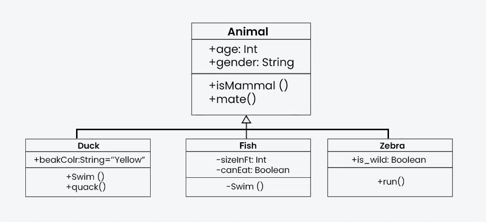
Here’s an example of a UML class diagram featuring multiple classes with an “inheritance” relationship:
§1 UML Class Diagram Overview #
A class diagram is a type of diagram that describes the structure of a system with a visual representation of its classes, attributes, methods, and the relationships among objects. A class diagram typically contains:
- Class Name: The name of the class.
- Attributes: The data members or properties of the class.
- Methods: The functions or operations that the class can perform.
- Access Specifiers: These define the visibility of the attributes and methods. Common access specifiers:
+for public-for private#for protected.
§2 Example Class #
Lets begin with a practical example. Here is a simple class prototype which represents a circle.
class Circle {
private:
    double radius;
    Point center;
    void myPrivateMethod();
public:
    void setRadius(double radius);
    void setCenter(Point center);
    double getArea();
    double getCircumference();
};
And here is how this Circle class would be represented in UML notation:
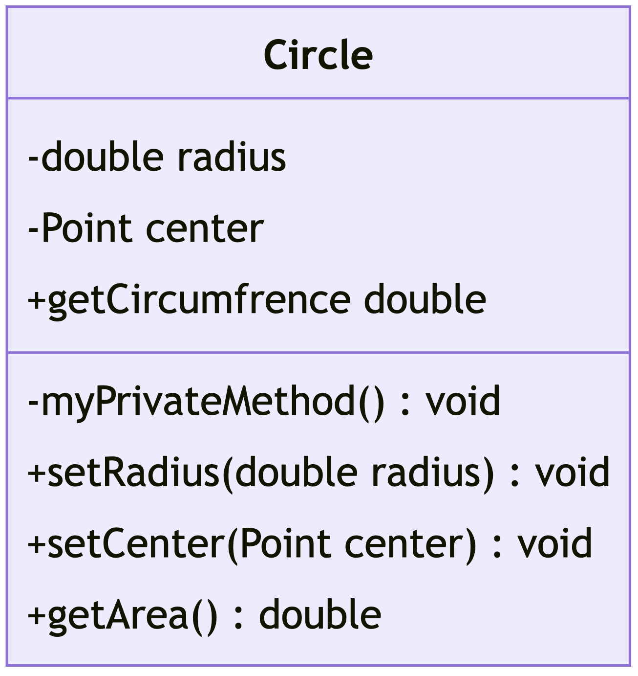
- The top compartment contains the name of the class. It is typically printed in bold and centered. It may also contain optional annotation text describing the nature of the class.
- The middle compartment contains the attributes (or data members) of the class. They are left-aligned.
- The bottom compartment contains the operations (or member functions) the class can execute. They are also left-aligned.
- All members show an access specifier on the far left of each member.
This class contains a member center which references another class, let’s add this Point class to the diagram:
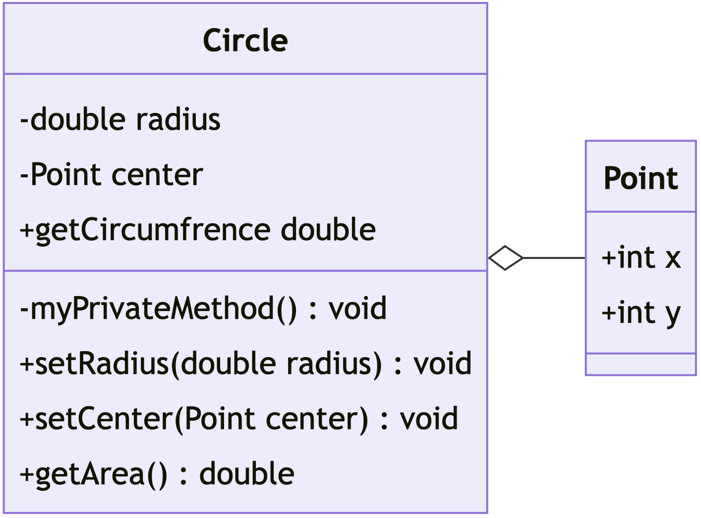
Even without code, with the UML diagram we can effectively communicate that the Point class has two member variables: x and y. The solid line with a white diamond connecting the two classes signifies an aggregation relationship between them, indicating that the Point class is a part of the Circle class, but can exist independently of the Circle class.
§3 UML Diagram Relationships #
Relationships are used to show how different elements within a system interact with one another. Specifically, UML relationships are essential for modeling the connections between classes, objects, and other components in a system. the above example demonstrates an “Aggregation” relationship, there are several different types of relationships that can be represented in UML.
Common UML Relationships:
| - Association: has a - Inheritance: is a - Realization: implements - Dependency: uses - Composition: contains a - Aggregation: has a |
|

- Association: “relates to” (a general relationship, where one class is related to another, but both can exist independently)
- Inheritance: “is a” (the subclass is a specialized version of the parent class, inheriting its attributes and behaviors)
- Realization: “implements” (used to indicate that a class implements the behavior specified by an interface)
- Dependency: “uses” (a temporary relationship where one class depends on another, but they are not tightly coupled)
- Composition: “owns a” or “contains a” (a strong “has a” relationship where the part cannot exist independently of the whole; if the whole is destroyed, the part is destroyed too)
- Aggregation: “has a” (a weaker “has a” relationship where the part can exist independently of the whole)
Some more examples of each relationship type:
- https://creately.com/guides/class-diagram-relationships/
- https://blog.visual-paradigm.com/what-are-the-six-types-of-relationships-in-uml-class-diagrams
§4 UML Diagram Creation #
There are many online tools that can be utilized to create UML diagrams. Here is a non-exhaustive list of options for creating diagrams:
- diagrams.net - A free diagram creation tool
- lucidchart.com - Another visual diagram creator
- asciiflow.com - A visual editor for ASCII diagrams
- mermaid.live - Converts code-like text input into diagrams
I used mermaid.live for creating the diagrams in this lab. If you use this, you will want to first check the docs
§5 Further Reading #
- Textbook: Appendix F
§6 Assignment #
For this lab, you will create a few UML diagrams to visualize the following, be sure to include Access Specifiers and relationships in your diagrams:
Part 1:
Create a UML diagram representing the following Book class:
class Book {
private:
  std::string title;
  std::string author;
  std::string ISBN;
  double price;

public:
  // Method to display book information
  void getDetails();

  // Method to set a new price
  void setPrice(double newPrice);

  // Method to get the price
  double getPrice();
};
Part 2:
Design a UML class diagram for the following classes and relationships:
- A
Teacherclass that has public attributesnameandsubject, and a methodteach(). - A
Courseclass that contains a publiccourseNameattribute and acourseDetails()method, as well as a reference to theTeacherclass as a member. - A
Studentclass that has reference to aCourseas a member, and additional attributesstudentNameandgrade, and methodsenroll()andviewGrade(). Be sure to use the correct relationships to link the classes together. Consider if the relationship between each class is a strong or weak connection, and if each class could exist without the others.
Write a short explanation of why you used a specific relationship for linking each class.
Part 3:
Create a UML class diagram for a Car class that has:
- Public Attributes:
make,model, andyear. - A reference to an
Engineclass that has attributestypeandhorsepower, and astartEngine()method. - References to a
Tireclass, with attributesbrandandsize, and ainflate()method. For this example, assume that theTireandEngineclasses cannot exist outside of aCar. This will affect the relationships between the classes.
Write a short explanation of why you used a specific relationship for linking each class.
For Submission: place all three diagrams and explanations on a document and submit as a single PDF.